Constructing the NA4RR Hex Beam Antenna
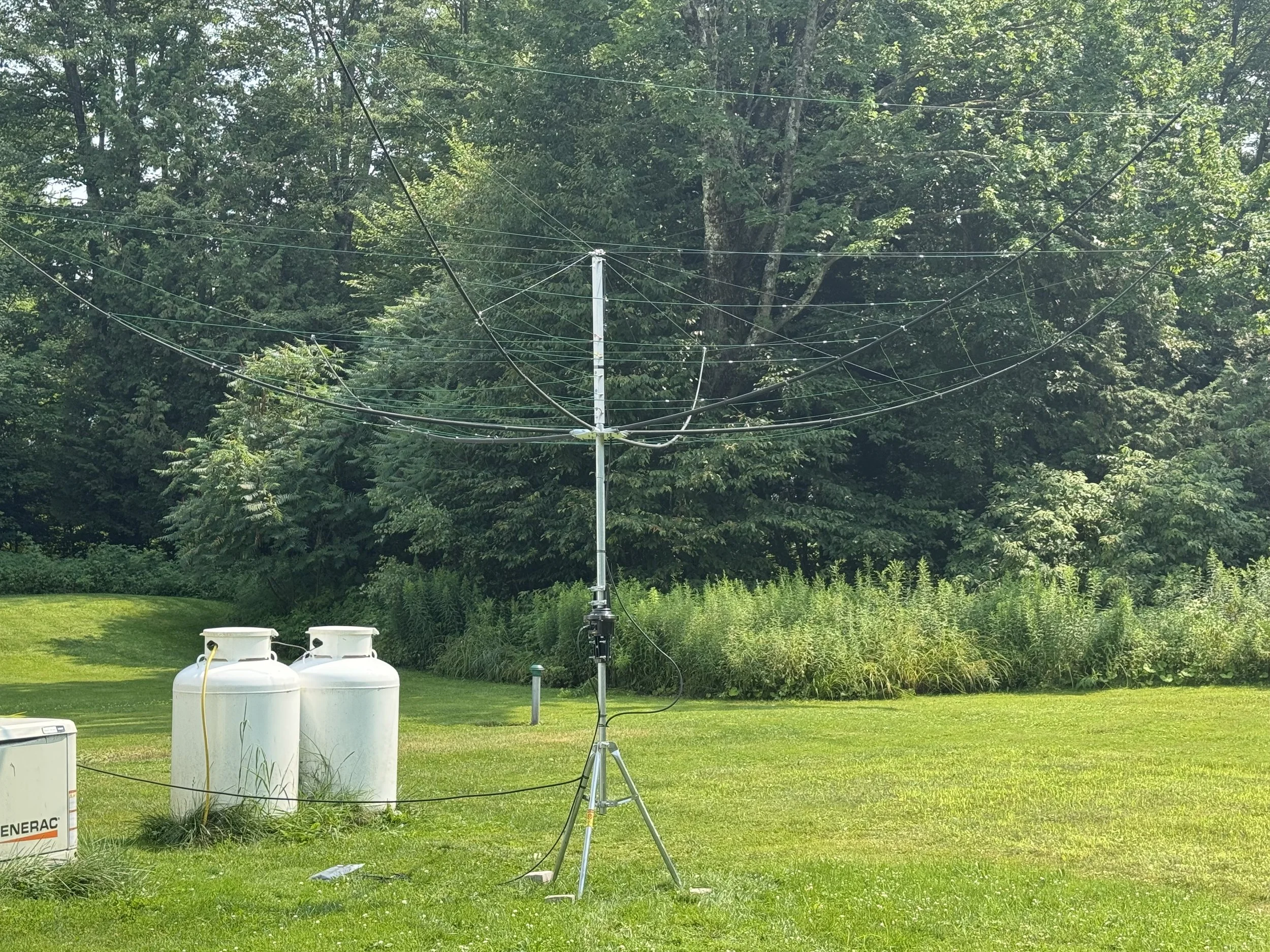
K9JY’s Hex Beam (not on the roof yet….)
I’ve wanted to have some sort of gain antenna to use besides my three vertical antennas. I’ve had a Rohn 45 tower and beam before and was very happy with that setup. But towers today, along with a decent yagi antenna, becomes spendy very quickly. Besides, I live in Nowhere, VT, and getting help to not only put up the tower and yagi as well as to have someone to maintain it going forward is not really in the cards.
So, the question was: How can I have a gain antenna that I can build and maintain myself? The answer was getting a Hex Beam from NA4RR. While it looks like an upside down umbrella, the Hex Beam is an effective two element beam on the bands. The NA4RR hex beam covers 20-6 meters. One of the important considerations was that I did not want to DIY this antenna. NA4RR’s antenna comes configured; no cutting wires or tuning; just follow the directions (with some important caveats to follow).
This article will look at the construction of the hex beam. I’ll cover performance of the beam as compared to my 43’ vertical with 60 radials in a different post. Like once I get it up on the roof….
Initial observations
The antenna comes in a single box, with the parts for the antenna well laid out inside. Everything is labeled and even color coded for easy identification.
Here is where my first hiccup occurred. NA4RR provides a great video of putting the antenna together. There’s also one sentence that gives you a link to the PDF instructions. I waited until the rest of my parts (tripod, rotor, coax, etc.) came from DX Engineering before I opened the box and downloaded the instructions. Opening the PDF for the instructions, I discovered that I should both prime and paint the spreaders for UV protection. I wish I would have downloaded the instructions because the video makes no mention of priming and painting the spreaders. In the instruction video, the spreaders are not painted.
The PDF instructions and the link therein suggest that the primer be allowed two full days to dry. The Rust-oleum primer and paint say to wait for 24 hours. Well, I let the primer dry for two full days and the paint dry for one day. Painting the spreaders, of course, makes sense and I highly recommend it. But I could have done all that while waiting for my delivery from DX Engineering and not lost the time.
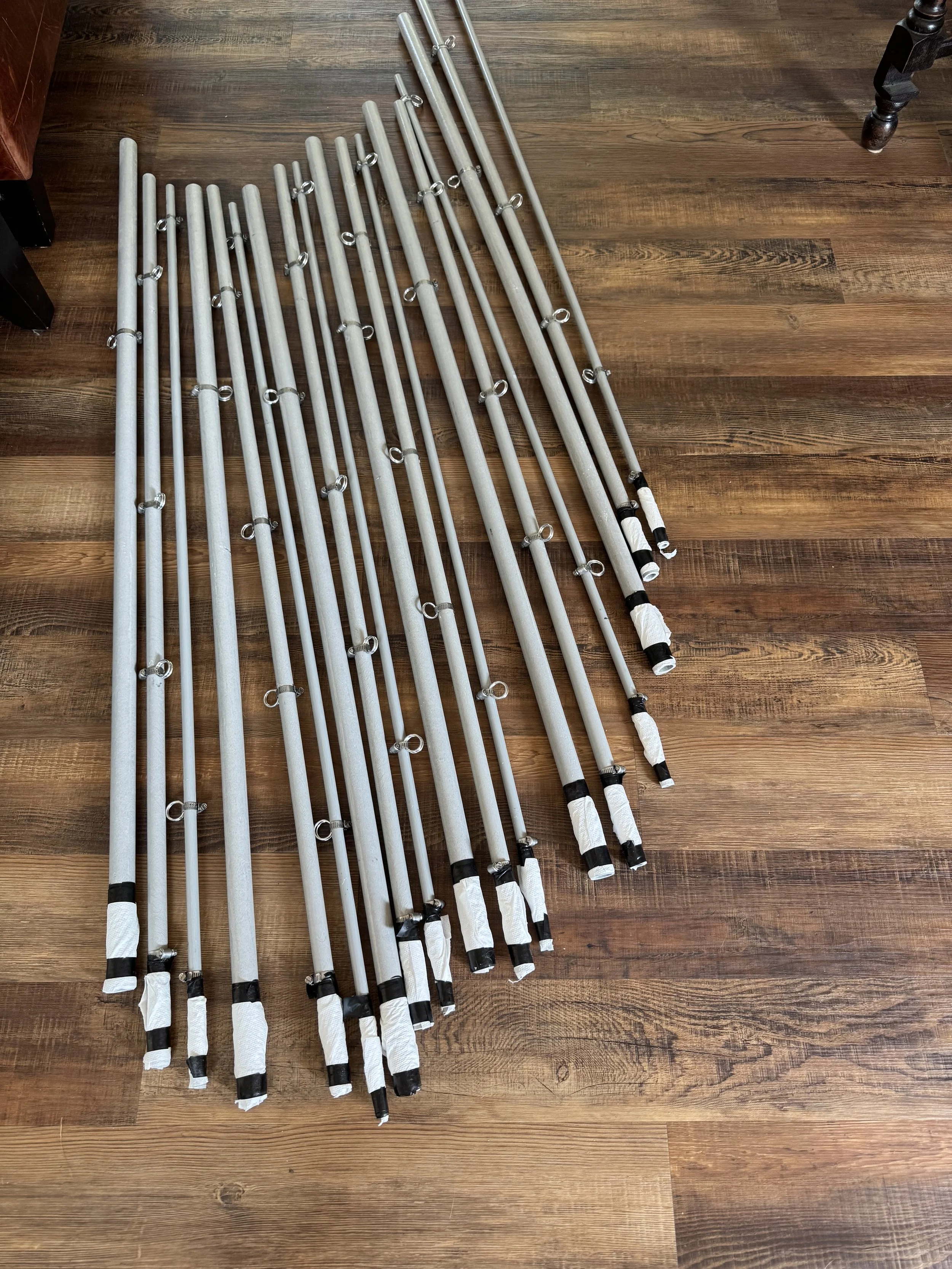
First, you need to protect the part of the spreaders being inserted into the other spreaders because the primer and paint can wreck the tolerances on which the spreaders are built and they won’t fit.
I used electrical tape and paper towels to protect the spreader’s insertion points. You can see the spreaders have washers that provide the length to be inserted to the next spreader. And the largest spreaders, that insert into the base plate, have been marked by NA4RR to show how far the spreader should be protected. This ended up being a problem.
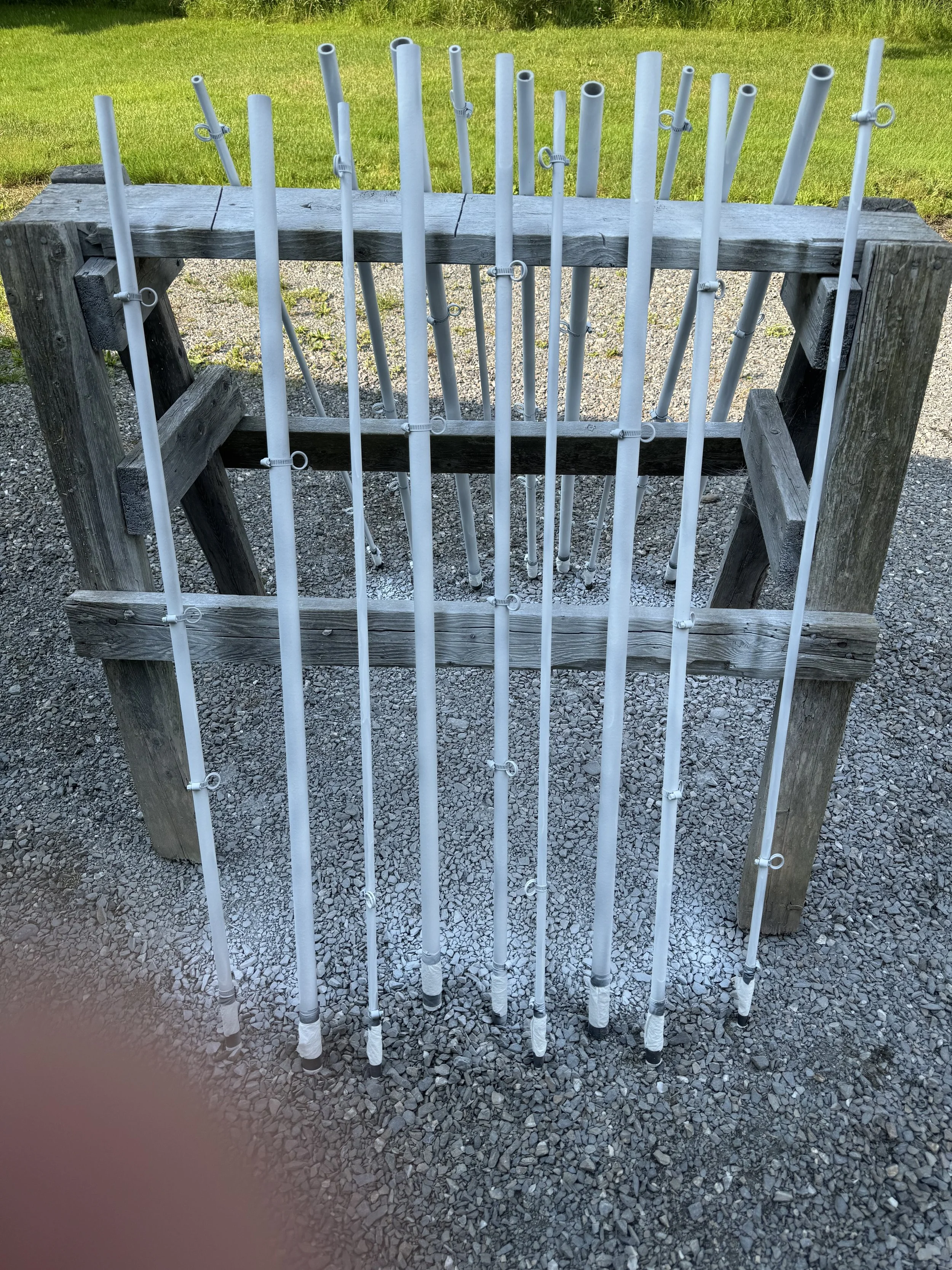
The priming station. The old wood sawhorse has been here since we moved in 3-years ago and I never found a use for it until now.
As noted before, I let this dry for two full day’s. This amount of priming took three cans of spray paint. I used the Universal Bonding Primer from my local ACE Hardware store. Then, after the two days, I moved into my garage because it was going to rain and completed the painting part. For that, I used Flat Black non-reflective finish. You can see in the top picture how it blends into the trees around my property. Here’s the painting station:
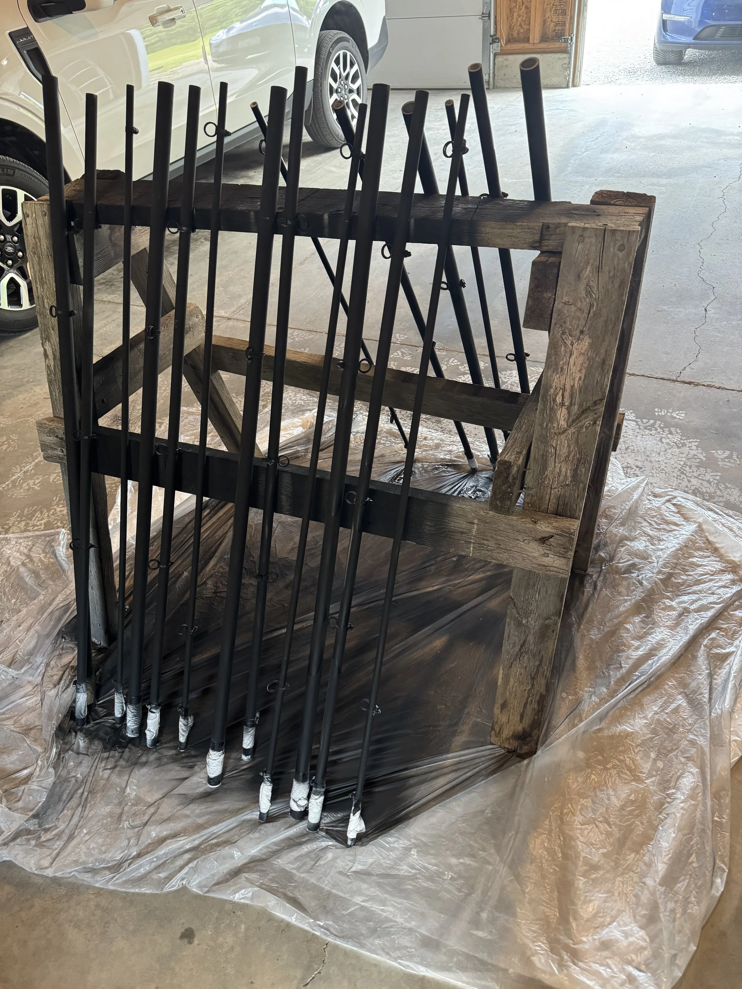
The painting station.
Building the Antenna
The next step was to lay out all of the parts on a tarp in the yard where I was going to build the antenna.
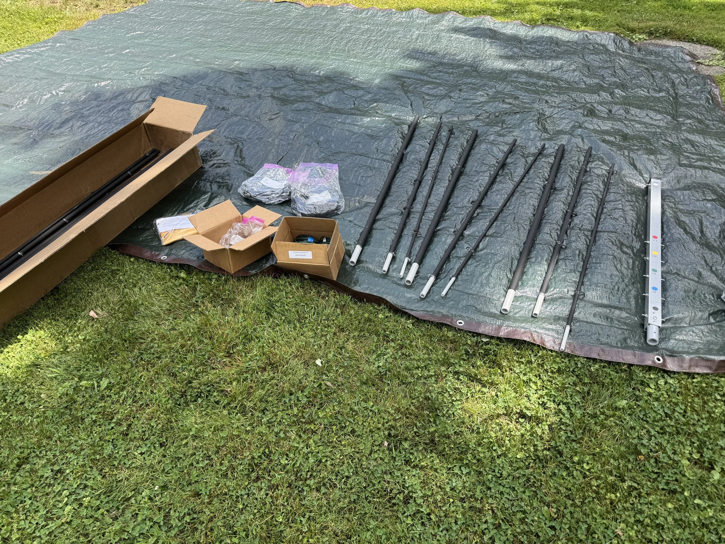
The parts laid out on the tarp. More spreaders in the box and the antenna wire and spreader ropes in their own boxes as shipped.
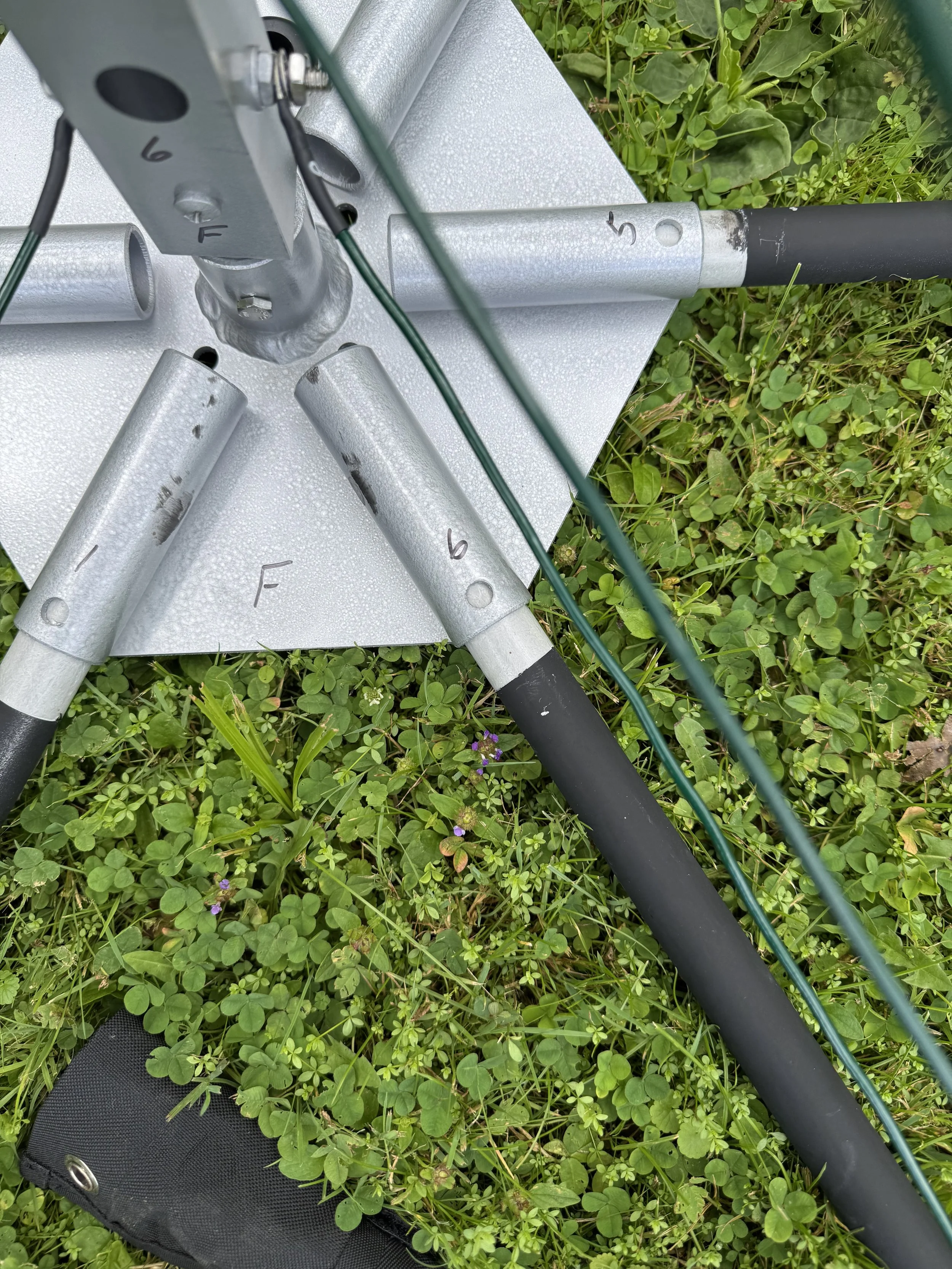
And here is the antenna base plate that the spreaders fit into along with the pipe that the wires attach to.
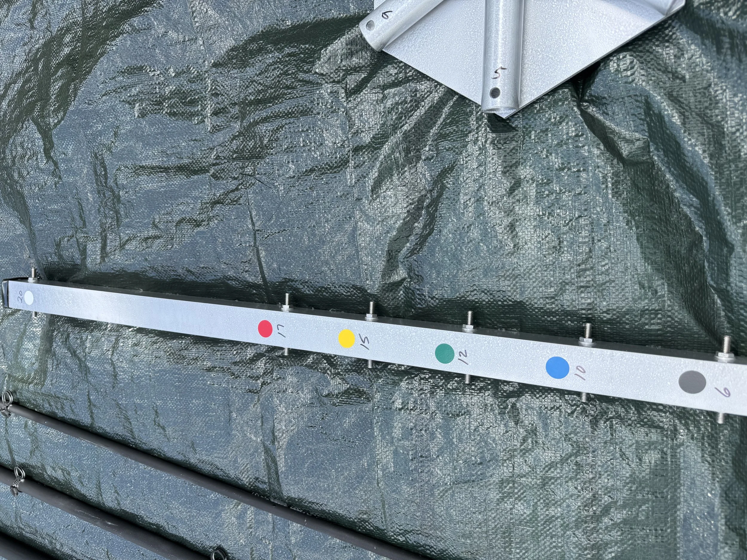
Notice the color coding for each of the bands. Plus notice the spreaders are numbered along with an F for the Front of the base plate (where the antenna is pointed).
The first step is to place the spreaders into the slots on the base plate. And here is where the directions were off. The problem is that the spreaders are supposed to fit up to the point of the paint where it was marked. But the base spreaders did not go into the antenna base that far - they were off by about an inch. They went in three inches, not four as marked. You can see that in the next picture (after I assembled the antenna).
You can see where paint is needed. To leave off the primer and paint is begging for your UV protection to break right at the base of the antenna.
My suggestion is to insert the base spreaders into the base antenna plate and take your masking from that point. It’s a hard stop at the back of the spreader in the base plate. I did this after I finished building it so I didn’t worry about waiting for more paint to dry…and then primed and painted the missing parts.
Support and Antenna Wire Build
Once the spreaders are in the base plate and all spreaders inserted inside each other, NA4RR suggests (and I agree) to put the base into a short mast (mine was two-feet) so the entire antenna is off the ground.
The instructions say to use, for example, a five gallon bucket and play sand to build this temporary structure. I’d highly suggest this method (though I went mast directly into the ground…but it wouldn’t stay upright…). So get your 5-gallon pail and enough play sand from your hardware store to set this up.
And the masts…well, that is an entirely different story further below.
Ice support cord installation
NA4RR offers Ice Support cords:
Set of 6 cords with hardware. These are installed in addition to the standard support cords. They connect from the top of the center post to half way down the spreader arms. They provide additional support to counteract the weight of accumulated ice and snow.
I bought these because I live five miles from the Canadian border and ice and snow are a thing here. But, really, why wouldn’t you want this additional support no matter where you live? High winds, hail, hurricanes…all would make having these support cords help keep your antenna together.
The installation issue here is that neither the video, nor the PDF instructions, tell you when you should install them on the antenna. I put the entire antenna together and then installed the cords. It was a small pain as all the antenna wires were already installed and moving around inside the six band wires was a little tricky for access.
Much better to install all of the support cords for the spreaders, then before installing any antenna wire, install the ice and snow support cords. This is much easier to install as you still have complete access between the spreaders to install the cords. And, with the cords in place, it’s easier to navigate the wires around the ice support cords.
Installing the antenna wire
The hardest part about installing the antenna wire is carefully unwrapping the wire without it getting tangled. The twenty meter wire is really long. Remember, you’re installing both the driven element and the reflector on the single wire broken up by cord so that each length is correct.
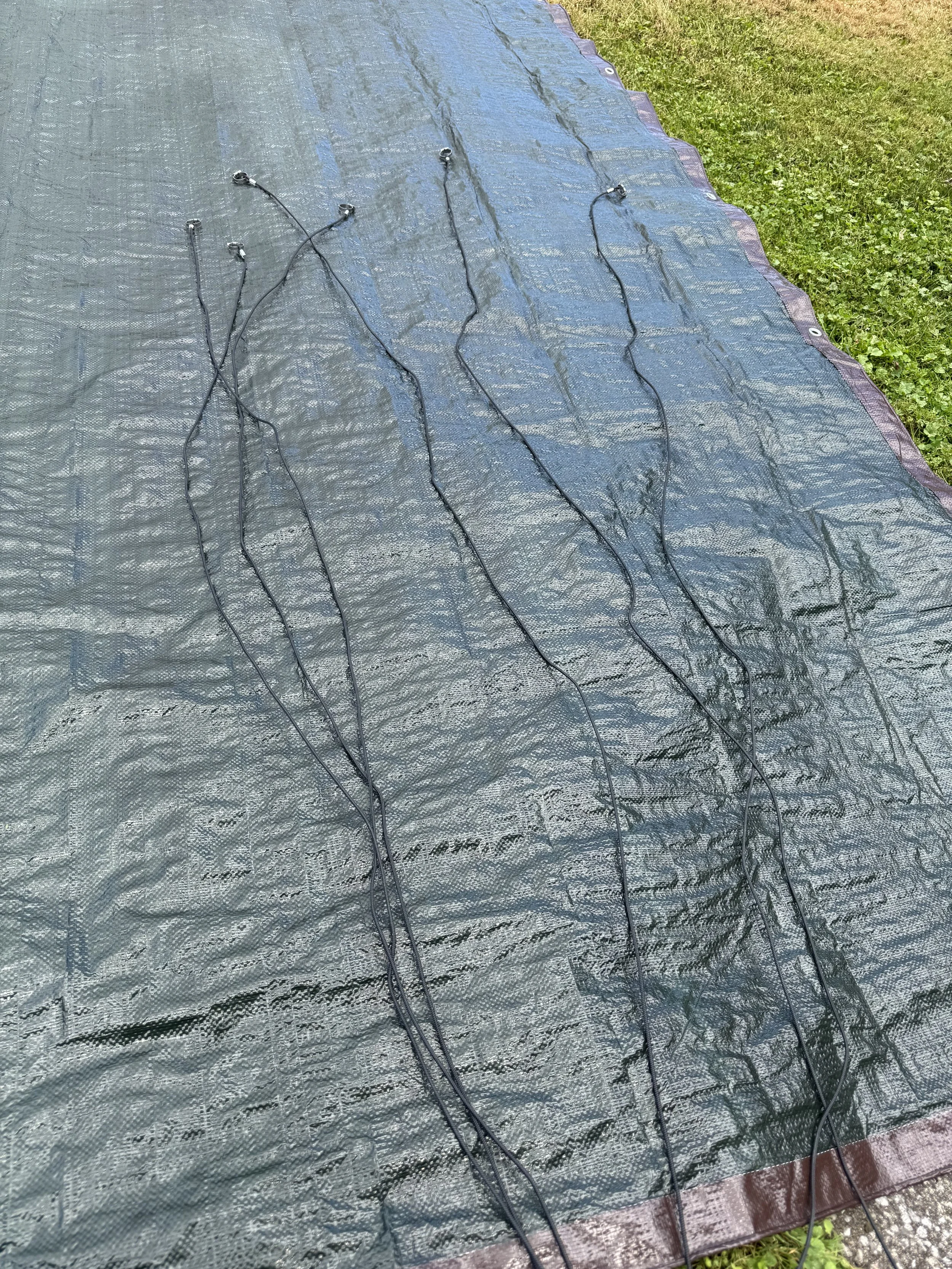
These are the Ice Support Cords, but it gives you an idea of the untangling that needs to be done for cords and antenna wire.
To be fair, NA4RR both labels the cords and antenna wire really well. The antenna wire ends are color coded to match the color coding on antenna base.
This is hard to describe, but NA4RR wraps the antenna wire in two separate, but unified pieces. What worked best for me was to take the wire without the ends part and slowly unravel one side of it fully out. Then go to the ‘ends’ bundle and take one of the ends and unravel it. Six meters is easy…but twenty meters is a challenge! Just be patient. On all of this. What you end up with are wires that are hand tightened to the antenna base:
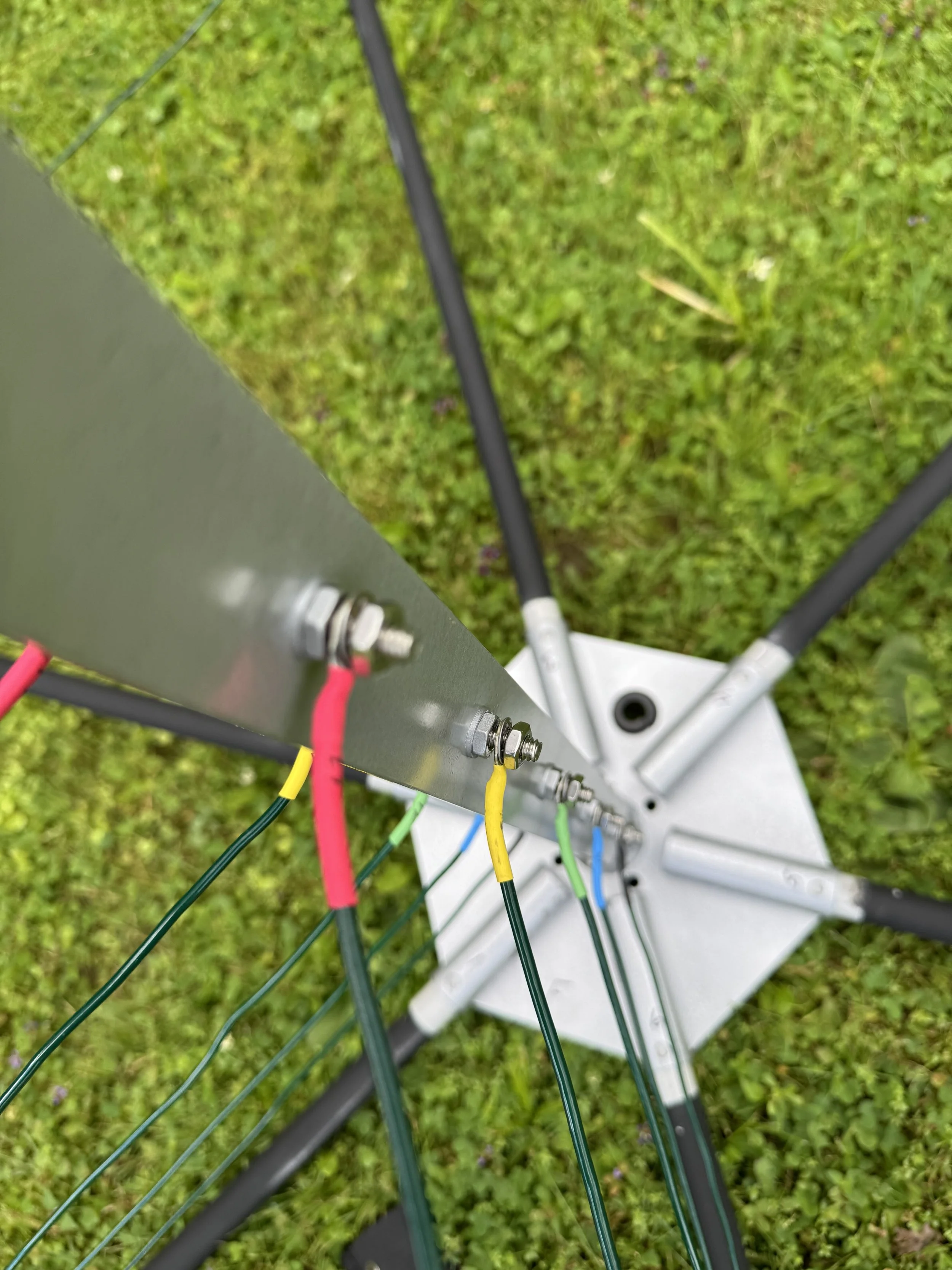
Notice the color coding by band on these hand tightened antenna wires.
I have two comments about this. First, I don’t remember and didn’t see in the PDF instructions to take the hand tightening to tightening everything down. Second, I highly recommend you put some Jet Lube SS-30 on each of the nuts to prevent oxidation from occurring over time.
And then tighten the bolts down.
This is the point where the PDF instructions and the video instructions end. Despite my commentary on the instructions, the antenna was easy to put together and most of the time (outside of painting) was spent on getting the support cords and antenna wire undone to the point of being able to use them. Taking the temporary mast off and out of the ground (or pail), you end up with a nice looking antenna below.
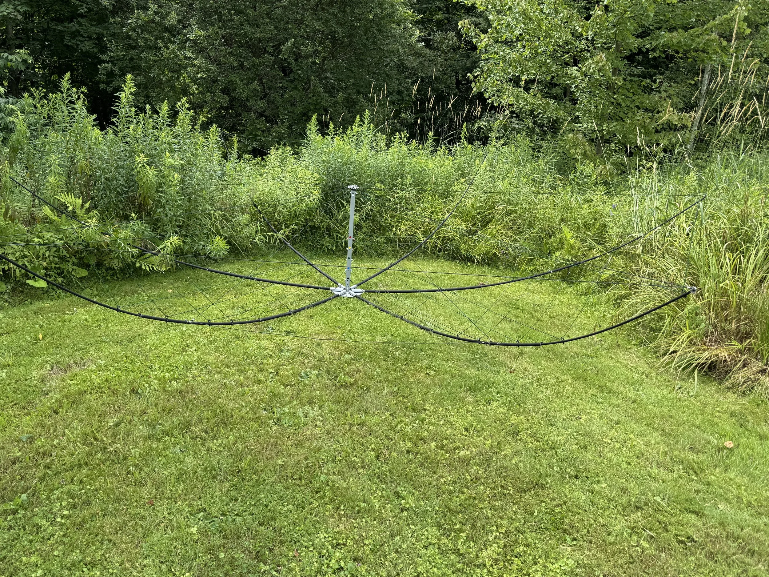
The completed antenna. Next up, the mast.
The Masts (please read)
The masts were the most frustrating thing about getting this antenna upright with the rotor. You have two masts:
One for the (in my case) tripod that will sit on the roof
One from the rotor to the antenna base
If you put the rotor inside a tower, there is only one mast, but size still matters as you’ll see.
NA4RR in the FAQ section suggests using the Yaesu 450 rotor which handles 5.4 square feet of wind load with just the mast, 10 square feet inside a tower (the antenna offers less than 5 square feet of wind load). That’s the one I bought from DX Engineering.
Also in the FAQ section, NA4RR notes that the system will use either a 1.5” or 1” diameter pipe for a mast. The 1” fits inside an opening on the antenna base while the 1.5” fits on the outside of that same pipe on the antenna base. My preference is the 1.5” mast - bigger, stronger. So I went to my ACE Hardware store and had them cut up a 10’ pipe into 3’, 4’ and kept the two foot section as well (I had to buy them in 10 ft sections…and I used the two foot section while building the antenna.
Now comes the comedy.
I get home with my masts and try to put the 1.5” into my tripod - and it doesn’t fit. It’s too big.
And at the antenna base, there are two holes that a bolt fits through so as to prevent the mast and antenna from turning independently. Except the 1.5” mast covers the holes so you can’t see where to drill.
Okay…the antenna also takes a 1” mast. So I go back to the hardware store and get the same cuts on a 1” mast.
I put the 1” mast into the tripod and it fits fine.
I put the other mast into the antenna base and it fits fine.
I put the masts into the rotor…and the mast is too small for the rotor. The specs say it will fit a 2.48” mast, but no minimum size. The pipes just spin in the rotor with the tightest settings. The FAQ section doesn’t not mention only 1.5” masts will fit into the rotor and not 1” masts.
So I go back to the hardware store - with my tripod - and ensure that a 1.25” mast will fit into the tripod. It does. So I cut up and pay for yet another pipe and come home. I put the 1.25” mast into the tripod and the bottom of the rotor and all fits fine. I put the 1.5” mast from the upper part of the rotor to the antenna base and it fits fine.
But, there are holes to drill:
A bolt goes through the bottom mast and the bottom part of the rotor so the bottom mast won’t spin.
A bolt goes through the upper mast where it connects to the antenna base. And the good news is that, since I already bought it, I can stick the 1” mast into antenna base, mark the holes because they show with the 1” mast, and then transfer that to the 1.5” mast that fits on the antenna base outside of those holes.
The bottom mast bolt hole goes through fine and the mast securely fits in the tripod and the bottom of the rotor.
After transferring the marks from the 1” mast to the 1.5” mast, the holes get drilled. And when I place the 1.5” mast on the antenna base, I can’t find the holes for the bolt.
It turns out that the 1” mast goes about a half inch further up into the antenna base than the 1.5” mast. So the holes are drilled incorrectly for the 1.5” mast.
I then have to measure from the bottom of the antenna base to where the holes are and then mark that distance on to the 1.5” mast (90 degrees from the initial holes….).
The holes get drilled again, but it turns out that the drill did not go straight through; necessary for the upper bolt to fit through.
Instead of drilling straight through (the drill wobbles too much on the other side of the pipe) this time I marked each side of the pipe and had that drilled. This, finally, worked.
Oh, did I mention that my drill bits wouldn’t go through the pipes? Yeah, I had to take the masts to Ace Hardware to get the holes drilled. Three times. Interestingly, they use the same drill, looked like the same drill bits, but theirs worked. Mine didn’t. Don’t count how many times I went to Ace Hardware (who were really, really helpful through all this…).
If you have a drill press, that would work because everything is held steady.
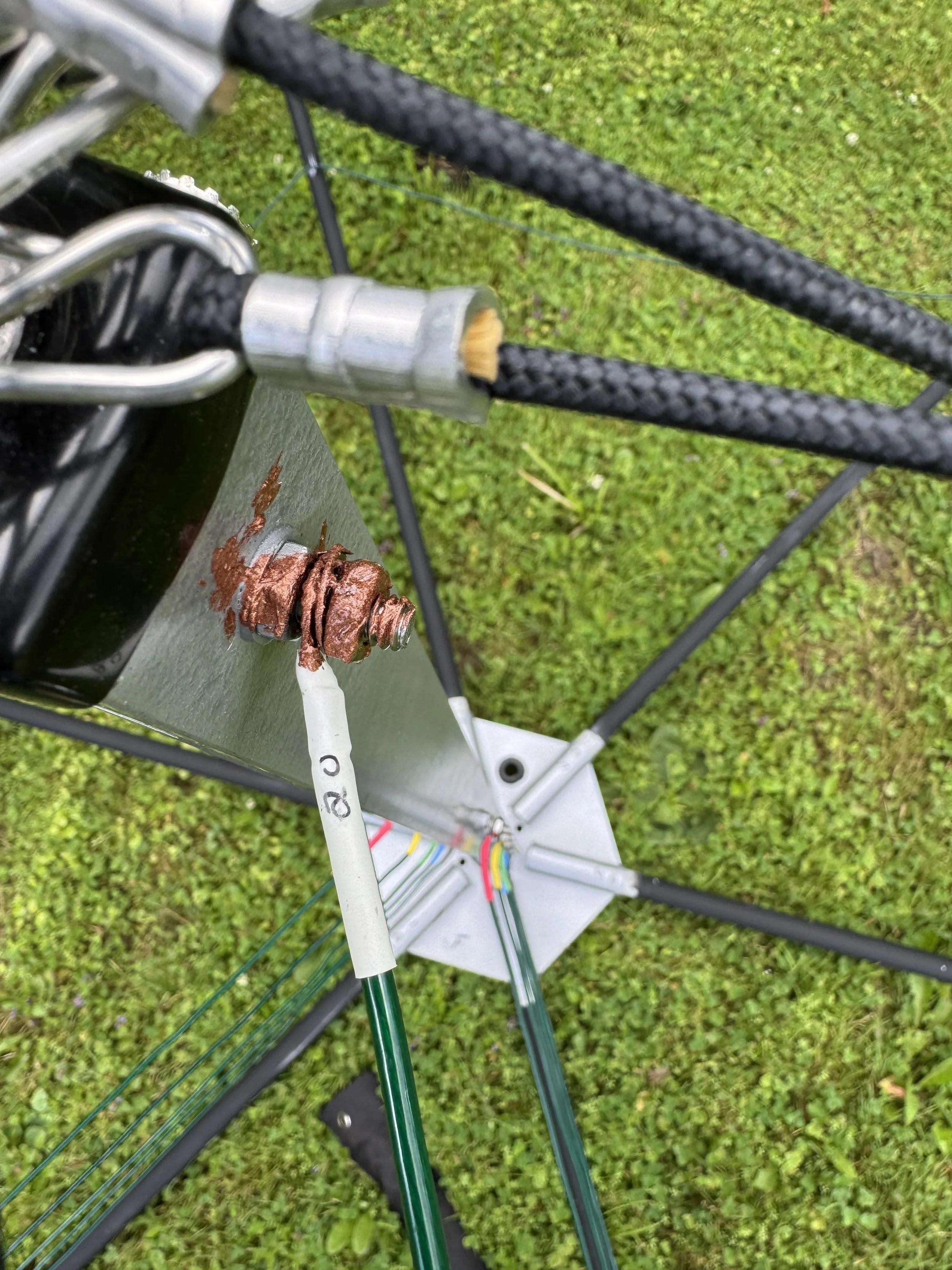
Connecting the coax to the antenna
The antenna connection is at the top of the antenna base and NA4RR recommends (and I agree) getting a 90-degree PL-259 / SO-239 to handle the coax. He doesn’t have any on his website (but you can see the picture of it with and without the 90-degree PL-259 / SO-239), so I ordered a pair from DX Engineering.
The coax cleverly goes through the antenna base after you remove the grommet there. So the coax comes up through the hole, the grommet is replaced, and then the coax connects to the SO-239 90-degree interface at the top of the antenna.
Now, you should buy the Balun Kit he recommends on his product page for your type of coax (I used RG-213). But when you look at his installation video for the Balun Kit, you’ll notice he’s doing that on his workbench. That’s good for showing you how to install it on the coax - the but the balun does NOT fit through the hole in the antenna base, even with the grommet removed.
Thus, you need to install the Balun Kit outside at the antenna, not inside at your workbench. If you install the balun on your workbench, you’ll have to take it all apart and then put it back on once your coax is through the hole in the antenna base.
(Make sure you take off the plastic covering for the balun kit; I missed that sentence in the instructions…).
Heat shrink
You wrap the Balun Kit in electrical tape and then you are supposed to apply the heat shrink around the balun kit and then heat it with a heat gun or equivalent.
There are two end pieces of heat shrink. One needs to go over the coax cable BEFORE you apply the Balun Kit. This protects the lower end of the balun. Then goes the main piece over the balun. Then the top uses the smaller heat shrink piece to cover the top end.
The problem with my installation is that the big heat shrink piece was too small to fit over the balun. This is with only one layer of tape over the balun. I tried a small cut to help it get over the balun, but it was still too small, by more than a quarter inch. I don’t know if NA4RR just picked the wrong size of the wrong size got put into my package, but it would not fit.
Consequently, I ordered two weatherproofing kits from DX Engineering (it takes two) and put in my own weatherproofing. The coax and the Balun Kit installation ended up looking like this:
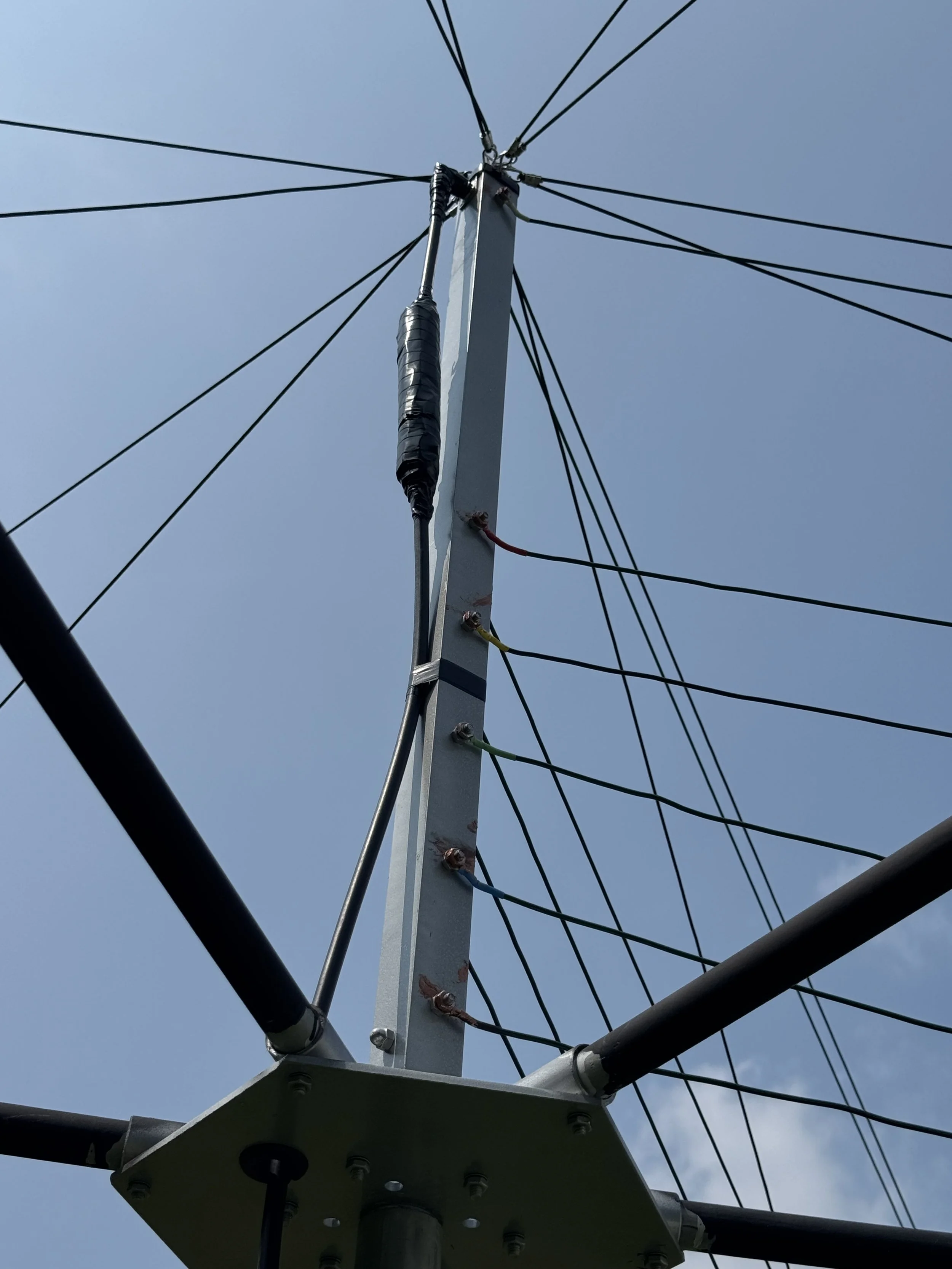
Balun Kit installed
One other point on weatherproofing: you need to weatherproof all the coax connections. That means where the coax connects to the top of the antenna base (see above) and where the coax connects to your lightning protector. Otherwise, water will get into the connectors and you’ll short out your connection to the antenna. That includes your electrical connections as mentioned above. You don’t want the connections to oxidize and ruin the performance of your antenna.
Conclusion
I hope that this article is helpful for those contemplating installing (any) hex beam. I’ve been critical of some items from NA4RR - the painting, the ice cords, the masts and mast holes, and the balun. These are things that can be easily added to instructions or to an installation video. Doing so would have saved me a lot of time and frustration.
But putting the antenna together itself - that was straightforward. NA4RR tried to make it as idiot-proof (I’m looking in the mirror here…) as possible. I’m not an expert on the quality of the parts or materials used, but they look, feel and install as though they are of good quality.
Once I get the holes drilled from my basement to my first floor office and my coax and rotor cables installed in my shack (it goes up from my basement to my office; it’s a whole other story…), I’ll report on the performance as you see it in the first photo, about 6-10 feet off the ground. And then I’ll report on the performance once on my roof, which is about 18 feet above the ground. All in all, the antennas should be about 25-30 feet off the ground once on the roof.